Fórum témák
- • Videoton RA 6363 és EA 6383 javítása
- • Folyamatábrás mikrokontroller programozás Flowcode-dal
- • LiFePo akkuk töltöttségének ellenőrzése
- • Mosógép vezérlők és általános problémáik
- • Kombikazán működési hiba
- • Felajánlás, azaz ingyen elvihető
- • Érdekességek
- • Két telefon összekötése
- • Audiofil, High End Audio
- • Villanymotor bekötése
- • Sztereó erősítő olcsón
- • V-FET és SIT erősítő kapcsolások
- • Mosogatógép hiba
- • Ponthegesztő készítése házilag
- • Erősítő mindig és mindig
- • Gázkazán vezérlő hibák
- • Alternativ HE találkozó(k)
- • Ki hol gyártatja a NYÁK-ot ?
- • Képmintagenerátor
- • Androidos okos telefonok
- • Muzeális készülékek-alkatrészek restaurálása
- • Akkumulátor töltő
- • Kamerás megfigyelőrendszer
- • Rendelés külföldről (eBay - Paypal)
- • Villanypásztor
- • LCD kijelző vezérlése, életre keltése
- • Napelem alkalmazása a lakás energia ellátásában
- • Szobatermosztát bekötése
- • Li-Po - Li-ion akkumulátor és töltője
- • I2C I/O port bővítés: MCP2317, MAX6956
- • Tápegységgel kapcsolatos kérdések
- • Oszcilloszkóp vétel, mit gondoltok?
- • Földelt kimenetű erősítők
- • Villanyszerelés
- • Autóelektronika
- • Futópad
- • Milyen csatlakozó ez?
- • Elfogadnám, ha ingyen elvihető
- • Klíma szervizelés, javítás
- • Mihez kezdjen manapság egy elektrotechnikai műszerész?
- • ESP32 flash problémák
- • Keltető hőfokszabályozó
- • NYÁK készítés CNC-vel
- • DC-DC konverter
- • Elektromos távirányítós kapunyitó
- • LED-es világítás
- • Kis teljesítményű 3 fázisú betáppal 1 fázisú nagy teljesítmény kivétele
- • LCD TV probléma
- • Számítógép hiba, de mi a probléma?
- • Rádió áthangolása, OIRT - CCIR konverter
- • Fejhallgató erősítő
- • Nyomtató probléma
- • Kivezérlésjelző, de nem LED-ekkel
- • Hűtőgép probléma
- • Vicces - mókás történetek
» Több friss téma
|
12f683 Sziasztok!
pic12f683 picet használok. A GPIO5 lábat kimenetként szeretném használni, de nem akar kimenetként működni. Igazából lóg a levegőben. A mainban lehet, hogy hiányzik valami.
void main() { OPTION_REG = 0x82; //megszakítás a felfutó élnél, előosztás 1/8 tmr0=255; // IOC= 9; // megszakítás engedélyezés a 0,3 bemeneteken // INTCON=0b11001000; //GIE és GPIE bitek engedélyével a perifériás megszakítás engedély INTCON=0b11101000; /* INTCON.GIE=1; //globális megszakítás engedély INTCON.PEIE=1; //perifériás megszakítás engedély INTCON.T0IE=1; //timer0 tulcsordulás megszakítás engedély //A T0IF lábat törölni kell megszakítás után INTCON.GPIE=1; //az input-output lábakon történő változás okozta megszakítás engedély //A GPIF lábat törölni kell megszakítás után */ OSCCON=0b01110001; // 8mhz belső oszcillátor CMCON0=7; //komparátor kikapcsolva ANSEL=0; //analóg csatornák kikapcsolva // 543210 //TRISIO=0b00001001; // 0,3 láb bemenet TRISIO=0x9; GPIO=0; GPIO.GP5=1; figyel=0; delay_ms(500);
Átírtam, de így sem megy.
HW_PWM_setup movlw b'00000101' movwf RE5PPS clrf CCPTMRS0 clrf CCPTMRS1 movlw .200 movwf T2PR movlw .125 movwf CCPR1L movwf CCPR1H movlw b'10001100' movwf CCP1CON movlw b'00000001' movwf T2CLKCON movlw b'10000000' movwf T2CON
Viszont közben lett egy másik probléma is. Beállítottam egy timer0 megszakítást, de ez sem működik. A szimulátor szerint a timer fut, de nem fut megszakításra, mert a bsf PIE0, tmr0IE nem hajtódik végre.
tmr0_setup movlw b'00000000' movwf T0CON0 movlw b'01000000' movwf T0CON1 bsf INTCON,GIE bsf INTCON,PEIE bsf PIE0,tmr0IE bcf IPR0,tmr0IP bsf T0CON0,T0EN
Szia.
Összedobtam egy példát, ami a timer0-át használja, kb. 5 perc múlva kikapcsolja a GP0 lábat, Proteusba teszteltem.
/* * File: main.c * Author: taki * * CPU: PIC 12F675 * FREQ: 4 MHz belső * Compiler: XC8 * IDE: MPLAB X v4.10 * * PIC 12F675 * ------------------ * --|VDD VSS|-- * --|GP5 GP0|-- LED+ * --|GP4 GP1|-- * --|GP3 GP2|-- * ------------------ * 5 perces időzítő példa, ami a timer0-át használja * kb 5. perc múlva kikapcsolja GP0-án a LED-et. * * Created on 2024. július 1. */ #include <xc.h> #pragma config FOSC = INTRCIO // INTOSC oszcillátor; GP4 - GP5 láb I/O #pragma config WDTE = OFF // Watchdog Timer Letiltva #pragma config PWRTE = OFF // Power-Up Timer Letiltva #pragma config MCLRE = OFF // GP3/MCLR láb digitális I/O, MCLR belsőleg VDD-re kötve) #pragma config BOREN = OFF // Brown-out Detect Letiltva #pragma config CP = OFF // A programmemória kódvédelme kikapcsolva #pragma config CPD = OFF // Az adatmemória kódvédelme kikapcsolva #define IDO 29856 // 5 perc = 300000ms tehát kb. 300000/10.048 = 29856 megszakítás unsigned int time = 0; //Megszakítások void interrupt isr(void) { if (T0IF == 1) // Timer0 megszakítás 10.048ms-kor { tmr0 = 99; // tmr0 regiszter feltöltése T0IF = 0; // A TM0 jelzőbit törlése if (time > 0) // Ha time értéke nagyobb mint 0 akkor { time--; // eggyel csökkentjük az értékét } else // Ha már nem nagyobb akkor kikapcsoljuk a GPIO0 lábat { GPIO0 = 0; // GP0 láb alacsony } } } //Főprogram void main(void) { VRCON = 0x00; // Voltage reference Letiltva CMCON = 0b00000111; // Comparator Letiltva ANSEL = 0x00; // A/D Letiltva GPIO = 0; // GPIO Törlése TRISIO = 0b00000000; // összes láb kimenet WPU = 0; // Felhúzó ellenállások letiltva INTCON = 0b10100000; // Globális Megszakítások Engedélyezve, tmr0 Megszakítás Engedélyezve tmr0 = 99; // tmr0 regiszter feltöltése, megszakítás minden 10.048ms-kor OPTION_REG = 0b00000101; // Timer0 Indítása, 1:64 előosztó beállítása time = IDO; // Az time változó feltöltése GPIO0 = 1; // GP0 láb magas while (1) { //Egyéb utasítások } }
Sziasztok!
Sikerült megszakítást kicsiholni picből de a megszakítás mintegy 7sec múlva indul el. Utána rendesen megy. Van rá magyarázat?
void interrupt() iv 0x0004 ics ICS_AUTO { if(T0IF_bit==1) { T0IF_bit=0; tmr0=6; rendben++; if(rendben==1000) //1s { rendben=0; ido++; // 120 2óra GPIO.GP2=~GPIO.GP2; } } } void main() { OPTION_REG = 0x82; tmr0=255; // IOC= 9; // megszakítás engedélyezés a 0,3 bemeneteken // INTCON=0b11001000; //GIE és GPIE bitek engedélyével a perifériás megszakítás engedély INTCON=0b11101000; /* INTCON.GIE=1; //globális megszakítás engedély INTCON.PEIE=1; //perifériás megszakítás engedály INTCON.T0IE=1; //timer0 tulcsordulás megszakítás engedély //A T0IF lábat törölni kell megszakítás után INTCON.GPIE=1; //az input-output lábakon történő változás okozta megszakítás engedély //A GPIF lábat törölni kell megszakítás után */ OSCCON=0b01110001; // 8mhz belső oszcillátor CMCON0=7; //komparátor kikapcsolva ANSEL=0; //analóg csatornék kikapcsolva TRISIO=0b00001001; // 0,3 láb bemenet GPIO=0; while(1) { if(ido>60) { GPIO.GP1=1; ido=0; delay_ms(500); GPIO.GP4=1; } /* if(GPIO.GP0==0) { GPIO.GP1=1; delay_ms(500); GPIO.GP4=1; } if(GPIO.GP3==0) { GPIO.GP1=0; delay_ms(100); GPIO.GP4=0; } */ } }
Sziasztok!
Megint bajom támadt a 12F683-mal. Nem tudok megszakítást produkálni. A config word 0FD4, ami 8MHz belső oszcillátort állít be.
int ido, rendben; //Timer0 //Prescaler 1:8; tmr0 Preload = 6; Actual Interrupt Time : 1 ms //Place/Copy this part in declaration section void InitTimer0(){ OPTION_REG = 0x82; tmr0 = 6; INTCON = 0xA0; } void Interrupt(){ if (T0IF_bit){ // TMR T0IF_bit = 0; tmr0 = 6; //Enter your code here rendben++; if(rendben==1000) //1s { rendben=0; ido++; // 120 2óra GPIO.GP2=~GPIO.GP2; } } } void main() { IOC= 9; // megszakítás engedélyezés a 0,3 bemeneteken INTCON=0b11001000; //GIE és GPIE bitek engedélyével a perifériás megszakítás engedély //A GPIF lábat törölni kell megszakítás után OSCCON=0b01110001; // 8mhz belső oszcillátor CMCON0=7; ANSEL=0; TRISIO=0b00001001; // 0,3 láb bemenet GPIO=0; InitTimer0(); }
Nem tudom hol hibáztam?
Ez volna a próbaprogram:
#pragma config FOSC = HS // Oscillator Selection bits (HS oscillator) #pragma config WDTE = OFF // Watchdog Timer Enable bit (WDT disabled) #pragma config PWRTE = OFF // Power-up Timer Enable bit (PWRT disabled) #pragma config BOREN = ON // Brown-out Reset Enable bit (BOR enabled) #pragma config LVP = ON // Low-Voltage (Single-Supply) In-Circuit Serial Programming Enable bit (RB3/PGM pin has PGM function; low-voltage programming enabled) #pragma config CPD = OFF // Data EEPROM Memory Code Protection bit (Data EEPROM code protection off) #pragma config WRT = OFF // Flash Program Memory Write Enable bits (Write protection off; all program memory may be written to by EECON control) #pragma config CP = OFF // Flash Program Memory Code Protection bit (Code protection off) #include <xc.h> #include <pic.h> #define uzemmod2 PORTBbits.RB5 // 0-100 C #define RD4 PORTDbits.RD4 //__CONFIG( FOSC_HS & WDTE_OFF & PWRTE_OFF & CP_OFF & BOREN_ON & LVP_OFF & CPD_OFF & DEBUG_OFF); #define _XTAL_FREQ 20000000 int i, n, k,u, m, o, csak; int long j; int t=0, flag=0; unsigned int t2cnt, sz; void __interrupt() megszak (void) { if(PIR1bits.TMR2IF) { t2cnt++; if(t2cnt==30000){t2cnt=0;flag=1;}// lej?rt 1 min PIR1bits.TMR2IF=0; } } void main() { // OPTION_REG = 0x55; // Set tmr0 configuration and enable PORTB pullups INTCON = 0b11000000; // ' Enable global interrupts, Disables all peripheral interrupts, disable timer0 interrupt //CMCON = 0x07 ; // anal?g kompar?torok kikapcsolva, RA0-1 digit?lis port! // timer2 be?ll?t?sa PR2=249; //timer2 250?rajel ut?n ujrakezdi a sz?mol?st T2CON= 0b01001001 ; //4 el?oszt? modul on 10 ut?oszt? PIE1bits.TMR2IE=1; // tmr2 irq enable CMCON=0b11000010; // CVRCON=0xC0; TRISB=0b11111111; TRISC=TRISD=0; TRISA0=TRISA1=TRISA2=TRISA3=1; while (1) { // if (uzemmod1==1) u=1; if (uzemmod2==1) { RD4=1; T2CONbits.TMR2ON=1; } if(flag) {RD4=0; } } }
Úgy tűnik ezzel működik:
PROCESSOR 18F25K50
#include <xc.inc>
goto start
ledRedOn:
bcf TRISC,6
return
ledRedOff:
bsf TRISC, 6
return
start:
bcf LATC, 6 ; Set up the red LED
; Enable Timer 0 as a 16-bit timer with 1:256 prescaler:
; since the instruction speed is 12 MHz, this overflows about
; every 1.4 seconds.
movlw 10000111B
movwf T0CON
mainLoop:
movf tmr0L, W ; Trigger an update of tmr0H
; Blink the red LED with a period of 1.4 s.
btfss tmr0H, 7
rcall ledRedOff
btfsc tmr0H, 7
rcall ledRedOn
goto mainLoop
end
Még mindíg a MPLAB X IDE V6.15 assembly-vel küzdök. Nem sikerül a fordítás. Újra installáltam, ellenőríztem a beállítási útvonalakat, de nem sikerül a fordítás. Néztem Youtube videókat is, bár többnyire csak régebbi verziókról van.
Ki tudná próbálni valaki pl az alábbival? Esetleg egy régebbi verzióval is?
#include <p18f25k50.inc>
org 0x2000
goto start
org 0x2020
ledRedOn:
bcf TRISC, 6
return
ledRedOff:
bsf TRISC, 6
return
start:
bcf LATC, 6 ; Set up the red LED
; Enable Timer 0 as a 16-bit timer with 1:256 prescaler:
; since the instruction speed is 12 MHz, this overflows about
; every 1.4 seconds.
movlw b'10000111'
movwf T0CON
mainLoop:
movf tmr0L, W ; Trigger an update of tmr0H
; Blink the red LED with a period of 1.4 s.
btfss tmr0H, 7
rcall ledRedOff
btfsc tmr0H, 7
rcall ledRedOn
goto mainLoop
end
Nem vagyok PIC-es, de szerintem:
1. Kell hogy legyen IRQ handler a timer interruptnak. Van? Ez vagy üres legyen, vagy a tmr0IF-et törölni kell benne: lásd adatlap, hogy ez magától törlődik, vagy ha nem, akkor hogyan kell tölölni?
2. Az INTCON-ban a GIE és a tmr0IE bit aktív kell hogy legyen, különben nem lesz timer overflow interrupt.
Én úgy tesztelném először, hogy egyáltalán működik-e a timer, hogy az IRQ-ban egy debug pint billegtetnék, és ezt megfigyelném voltmérővel, vagy szkóppal. Ha ez már biztosan működik, akkor utána vinném csak altatásba a procit.
Szerk.: Bakman válasza érvénytelenítette amit írtam, de már nem törlöm. A hozzászólás módosítva: Okt 29, 2023
Szia!
tmr0-val külső jelet számoltatsz/figyelsz ?! A hozzászólás módosítva: Okt 29, 2023
tmr0-t is be lehet állítani kerek frekvenciára egy sor c-vel, meg némi matekkal.
Csak ahogy mást is, ennek a fránya picnek is az elején kellene kezdeni a tanulását mert igy csak egy sötét folyosón szédelegsz.
Megnézted a teljes beállításom és kódot a lap tetején lévő első hozzászólásban?
Megszakításban az újra töltés:
if (INTCONbits.tmr0IF) { tmr0L = 0x01; // 200nS / megszakítás Timer0Count++; INTCONbits.tmr0IF = 0; // clear the flag }
Ez 256szor fut le?
Az elő töltés határozza meg, hogy mennyi ideig tart 1 megszakítás nem?
Mindjárt meg méreg egy szkóppal, hogy milyen ciklussal villog a led a megszakításba.
Idézet:
„Timer0 megszakításának ideje (feljebb a teljes kód): FOSC/4/2/1 vagy is 40MHz/4/2/1 = 5MHz és ebből jön ki az idő, ami 1/5MHz = 200nS”
Szerintem itt van az amit elnéztél. Ha a Timer0 8 bites üzemmódban van, és tmr0 regiszterrel nem csinálsz semmit, akkor a beállításod szerinti megszakítási időd 200nS*256. Azaz 51,2usec lesz.
Indítok egy timer0-át 8bit-es módban. Beállítottam a leggyorsabb megszakításra, amely minimum 200nS / megszakítás. A megszakításban egy változót növelek.
1. timer0 indul
2. 1 byte adat lekérése SPI x 100 alkalom
3. timer0 leállít
Timer0 adatát megkapom: 128nS
Ez úgy jön ki, hogy timer0-ban növelt változó értéke 0.64, ezt úgy kaptam meg, hogy egymás után 100 alkalommal kérdezem le ugyan azt, majd ezt átlagolom. így jön ki a 0.64.
Timer0 200ns/megszakítás, 200*0.64 = 128nS
Minden más értéket is ugyan így mértem.
// Időméréshez látrehozott megszakítás void HighIntTimer0(void) { // Számoláshoz, 8bit-es mód // (FOSC/4) / Prescaler / tmr0H tmr0L // (40M/4) / 2 / 1 INTCON2bits.tmr0IP = 1; // Timer0 megszakítás magas prioritású legyen T0CONbits.tmr0ON = 0; // Timer0 kikapcsolva T0CONbits.T08BIT = 1; // 8 bites mód kiválasztás T0CONbits.T0CS = 0; // Meghajtás belső órajelről T0CONbits.T0SE = 0; // Külső órajel fel- vagy lefutó élének választása T0CONbits.PSA = 0; // Előosztás bekapcsolása //Előosztási arány beállítása (000 = 1:2, 001 = 1:4, 010 = 1:8, 011 = 0:16, // 100 = 1:32, 101 = 1:64, 110 = 1:128, 111 = 1:256) T0CONbits.T0PS2 = 0; // Előosztás 1:2 osztásra állítása T0CONbits.T0PS1 = 0; T0CONbits.T0PS0 = 0; INTCONbits.tmr0IE = 1; // Timer tiltása //tmr0H = 0xCD; tmr0L = 0x01; // 200nS / megszakítás }
Mérés:
HighIntTimer0(); Timer0Count = 0; MemCim.value = 0x259; T0CONbits.tmr0ON = 1; Sample = MemRead(MemCim); // 128nS alatt fut le Sample = MemRead(MemCim); Sample = MemRead(MemCim); Sample = MemRead(MemCim); Sample = MemRead(MemCim); Sample = MemRead(MemCim); Sample = MemRead(MemCim); Sample = MemRead(MemCim); Sample = MemRead(MemCim); Sample = MemRead(MemCim); // ...még 10 ilyen 10-es blokk lefele T0CONbits.tmr0ON = 0;
Megszakítás:
if (INTCONbits.tmr0IF) { tmr0L = 0x01; // 200nS / megszakítás Timer0Count++; INTCONbits.tmr0IF = 0; // clear the flag }
Breakpointtal állítom le a programot, debug módban. A hozzászólás módosítva: Jan 19, 2023
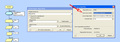
Jobb klikk a tmr0 megszakításra -> Tulajdonságok -> Tulajdonságok gomb.
Clock Source Select: Transition on T0CKI pin helyett Internal clock (CLKO) A hozzászólás módosítva: Nov 9, 2022
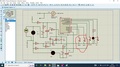
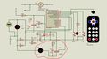
Dear friend, hardware testing is time taking and little hard job and remote in proteus is not functioning perfectly, please let me know if we attached two toggle swiches on free port as shown in attached screen shot,port RC0 SW1 is for ON and port RC2 SW2 is for OFF for triac2, then what ia modification in codes in main.c, if it is possible then i can test in proteus simulation software,
PLEASE MODIFY THE CODES: /******************************************************************************** * Fan Controller * * * * This program is free software: you can redistribute it and/or modify * * it under the terms of the GNU General Public License as published by * * the Free Software Foundation, either version 3 of the License, or * * (at your option) any later version. * * * * This program is distributed in the hope that it will be useful, * * but WITHOUT ANY WARRANTY; without even the implied warranty of * * MERCHANTABILITY or FITNESS FOR A PARTICULAR PURPOSE. See the * * GNU General Public License for more details. * * * * You should have received a copy of the GNU General Public License * * along with this program. If not, see <https://www.gnu.org/licenses/>. * * * * Date : Friday, 21 January 2011 * * Author : C.V.Niras/VU3CNS * * Copyright : (C) 2010 C. V. Niras * * Email : cvniras@gmail.com * * Processor : 12F675 * * First Release : 23/01/2011 * * Ver : 0.7 * * Change History: * * Rev Date Description * * 0.5 06/03/2011 First stable release * * 0.6 08/03/2011 Bug fixed - Can't swich on by CH+, when turned * * off by set speed to 0 * * 0.7 14/06/2011 Trigger off delayed for full speed (low firing * * angle) to reach the TRIAC latch current * * * *********************************************************************************/ #include <pic.h> #include "type_def.h" #include "remote_commands.h" #if defined _12F675 __CONFIG(WDTDIS & MCLRDIS & INTIO & BORDIS & UNPROTECT & PWRTEN); #define IsIRDataBitHigh() GPIO3 == 0 // Inverted logic #define SW_UP _GPIO,0 // Up switch #define SW_DN _GPIO,2 // Down switch #define LEDOn() GPIO1 = 1 // LED #define LEDOff() GPIO1 = 0 #define TriacOn() GPIO5 = 0 // Triac #define TriacOff() GPIObits.GPIO5 = 1 #define TRIAC GPIO5 // Triac pin #endif #if defined _16F676 __CONFIG(WDTDIS & MCLRDIS & INTOSCIO & BORDIS & UNPROTECT & PWRTEN); #define GPIO PORTA #define TRISIO TRISA #define GPIF RAIF #define GPIE RAIE #define IsIRDataBitHigh() PORTAbits.RA3 == 0 // Inverted logic #define SW_UP _PORTA,0 // Up switch #define SW_DN _PORTA,2 // Down switch #define LEDOn() PORTAbits.RA1 = 1 // LED #define LEDOff() PORTAbits.RA1 = 0 #define TriacOn() PORTAbits.RA5 = 0 // Triac #define TriacOff() PORTAbits.RA5 = 1 #define TRIAC PORTAbits.RA5 // Triac pin // v Added to handle triac2 #define Triac2On() PORTCbits.RC5 = 0 // Triac2 #define Triac2Off() PORTCbits.RC5 = 1 #define TRIAC2 PORTCbits.RC5 // ^ Added to handle triac2 #endif __EEPROM_DATA(5, 1, 1, 255, 255, 255, 255, 255); __IDLOC7('0','.','7','B'); #define TIMER_ENABLE // Enable timer // -- Chip Configurations -- #define _XTAL_FREQ 4000000 #define ZC_PIN_MASK 0x10 // Pin used for zero cross detection #define IR_PIN_MASK 0x08 // IR sensor output #define TIME_COUNT 6866 // Number of Timer1 overflows in an hour #define ANY_KEY Key & 0x80 #define UP_KEY Key & 0x01 #define DN_KEY Key & 0x02 // Timer 1 is the time base, 1 bit time = 8us; the NEC physical bit time is 560us = 70 Timer 1 // The following time are set with a +/- 20% tolerance #define IR_MARK_MIN_TIME 787 #define IR_SPACE_MIN_TIME 219 #define MIN_IR_BIT_TIME 56 #define MAX_IR_BIT_TIME 84 // -- End of Chip Configurations -- #define IRRx Flag.b0 // New IR bit received #define IRNewHit Flag.b1 // A new IR command received #define Error Flag.b2 // General error flag #define IRCmdRepeat Flag.b3 // A IR repeat command received #define StartFan Flag.b4 // Indicate to start the fan #define EEPromWrite Flag.b5 // Indicate to write to EEPROM #define UnknownCmd Flag.b6 // Unused IR command #define EETimeUpdate Flag1.b0 // Indicate to update time in eeprom #define IR05Seconds Flag1.b1 // A 0.5 seconds of IR inactivity, used to clear IR command repeate flag #define ClearLED Flag1.b2 // Need to turn off LED #define FanOn Status.b0 // Fan Running #define TimerRunning Status.b1 // Timer Running #define AddZeroToIRData() IRData._dword >>= 1 // Add a 0 bit to IR data #define AddOneToIRData() IRData._dword >>= 1; IRData._dword |= 0x80000000 // Add a 1 bit to IR data // NEC IR protocol states typedef enum _NEC_STATES { IR_IDLE, IR_MARK, IR_SPACE, IR_HIGH, IR_LOW, IR_REPEAT } NEC_STATES; // V A R I A B L E S //const unsigned char STable[10] = {0, 157, 165, 173, 181, 188, 195, 205, 216, 252}; // Modified to latch low power (load) fans low firing angle (on full speed) const unsigned char STable[10] = {0, 157, 165, 173, 181, 188, 195, 205, 216, 234}; near volatile BYTE Flag, Flag1, Status; near NEC_STATES IRState; unsigned char IRDataCount, PhaseAngle, Speed, Time, Count; volatile near unsigned char EECounter, Ticks, Key, KeyCount; volatile unsigned int IRTime, TimeCounter; DWORD IRData; // F U N C T I O N P R O T O T Y P E S void IRHandler(void); void NECDecoder(void); void InitIR(void); void SetSpeed(void); void OffTimer(void); void OnTimer(void); void SetTimer(void); void GetEEVariables(void); void SetEEVariables(void); void KeyDelay(void); void interrupt isr(void); void Delay2s(void); // M A I N void main(void) { #asm call 0x3ff bsf STATUS, 5 movwf OSCCAL & 0x7f bcf STATUS, 5 #endasm GPIO = 0; // Clear PORT // v Added to handle triac2 PORTC = 0; // ^ Added to handle triac2 TriacOff(); // Triac off TRISIO = ZC_PIN_MASK | IR_PIN_MASK | 0x05; // IR, Zero cross and swiches // v Added to handle triac2 TRISC = 0; // ^ Added to handle triac2 WPU = 0x05; // Weak pull up enabled for wwitches IOC = ZC_PIN_MASK | IR_PIN_MASK; // Interrupt on change is enabled for GPIO2, GPIO4 ANSEL = 0x00; // All are digital i/o CMCON = 0x07; // Comparators off INTCON = 0x68; // Enable PEIE, Timer0, Port change interrupts OPTION_REG = 0x05; // INT falling edge, Prescaler 1:64 T1CON = 0x31; // Prescaler 1:8, internal clk, TMR1ON LEDOn(); Flag._byte = 0; // Initialise flags and variables Flag1._byte = 0; InitIR(); GetEEVariables(); // Read variables eeprom IRState = IR_IDLE; // Init IR state if(FanOn) StartFan = 1; FanOn = 0; // This created a fresh start #ifdef TIMER_ENABLE if(TimerRunning) // If already started, set the time again SetTimer(); #endif GIE = 1; // Enable interrupts SetSpeed(); // Set the speed LEDOff(); // Turn off LED Count = Time << 1; // Count = Time * 2, i.e turn on/off Ticks = 0; do { NECDecoder(); // Decode NEC formatted IR data if(IRNewHit) // Is any new data? { IRNewHit = 0; // Y. Clear flag IRHandler(); // Do the command } if(IRCmdRepeat) // As long as the repeat command present { // do not turn of LED IRCmdRepeat = 0; Ticks = 0; // for the same clear Ticks } if(EEPromWrite) { EEPromWrite = 0; // Clear eeprom update flag SetEEVariables(); // Write variables if necessory } if(ClearLED) { if(Ticks & 0x20) // If remote command received, turn off LED after only { // few ms (~320ms) ClearLED = 0; LEDOff(); } } #ifdef TIMER_ENABLE else if(TimerRunning && (Ticks & 0x40)) // If timer is running and a short time expired (640ms) { // used to blink LED to show the time remaining if(Count == 0xF7) // Reload counter to show the time, after a certain time gap { Count = Time << 1; // Count = Time * 2, i.e turn on/off LEDOff(); // Ensure LED is off } if(!(--Count & 0x80)) // Blinks the LED till counter become -ve { if(Count & 0x01) { // On odd numbers in counter LED on LEDOn(); } if(!(Count & 0x01)) { // For even numbers LED off LEDOff(); } } Ticks = 0; // Reset ticks }//if(TimerRunning && (Ticks & 0x40)) #endif if(KeyCount >= 4) // Has key pressed for a short time? { if(UP_KEY) // Y. Check for Up key press { StartFan = 1; // Y. Up key pressed, inc the speed Speed++; } if(DN_KEY) // Check for a down key press { StartFan = 1; // Y. Down key pressed, decrement the speed Speed--; } if(StartFan) // If any key pressed, do the action { SetSpeed(); KeyDelay(); // Give a delay beore the next check } } }while(1); }// main // F U N C T I O N S /** The function is used to decode IR commands and make changes required */ void IRHandler(void) { if(!(IRData.byte0 ^ IRData.byte1) == 0) // Address and its compliment match { if(IRData.byte0 == 0) // Address is zero { if(!(IRData.byte2 ^ IRData.byte3) == 0) // Command and its compliment match { UnknownCmd = 0; switch(IRData.byte2) { case VOL_PLUS: StartFan = 1; Speed++; break; case VOL_MINUS: StartFan = 1; Speed--; break; case DIGIT0: Speed = 0; OffTimer(); break; case DIGIT1: StartFan = 1; Speed = 1; break; case DIGIT2: StartFan = 1; Speed = 2; break; case DIGIT3: StartFan = 1; Speed = 3; break; case DIGIT4: StartFan = 1; Speed = 4; break; case DIGIT5: StartFan = 1; Speed = 5; break; case DIGIT6: StartFan = 1; Speed = 6; break; case DIGIT7: StartFan = 1; Speed = 7; break; case DIGIT8: StartFan = 1; Speed = 8; break; case DIGIT9: StartFan = 1; Speed = 9; break; case CH_MINUS: FanOn = 0; OffTimer(); break; case CH_PLUS: if(Speed == 0) Speed++; StartFan = 1; break; case PREV: if(FanOn) Time--; SetTimer(); break; case NEXT: if(FanOn) Time++; SetTimer(); break; case EQ: OffTimer(); break; case PLAY: OnTimer(); break; // v Added to handle triac2 case CH100: Triac2On(); break; case CH200: Triac2Off(); break; // ^ Added to handle triac2 default: UnknownCmd = 1; break; } if(!UnknownCmd){ LEDOn(); // A new command received ClearLED = 1; // Clear LED after a little time Ticks = 0; // Reset timer ticks SetSpeed(); } }// if((IRData.byte0 ^ IRData.byte1) == 0) }// if(IRData.byte3 == 0) }//if((IRData.byte3 ^ IRData.byte2) == 0) } /** Off the timer, without changing previous set time */ void OffTimer(void) { TimerRunning = 0; // Turn off timer Time = eeprom_read(1); // Read the eeprom, value EETimeUpdate = 1; // Update time in the eeprom EECounter = 0; // Clear the eeprom counter to update eeprom } /** On timer, start with the previous set time, if the timer is not running */ void OnTimer(void) { if(FanOn == 1) // Only start Timer when fan on { if(!TimerRunning) // Nothing to do if already started { TimerRunning = 1; // Start the timer Time = eeprom_read(1); // Get time eeprom if(Time == 0) // If zero, switch on timer with a non zero value, i.e one hour Time++; TimeCounter = TIME_COUNT; // Reload the counter EETimeUpdate = 1; // Update time in the eeprom EECounter = 0; // Clear the eeprom counter to update eeprom } } } /** Set the counters for the timer. When the counter reached zero, the fan will be turned off If the timer not running, it reload time value with the last saved value the eeprom, otherwise adjust counters as required, and clear eeprom counter to update time value in the eeprom, for the same it set a EETimeUpdate flag */ void SetTimer(void) { if(Time & 0x80) // A neg, so clear it Time = 0; if(Time > 8) Time = 8; // Max 8 hours if(FanOn == 0) // Nothing to do if fan is not running return; if(!TimerRunning && (Time != 0)) { // If decrementing, and time reached zero, on further Time = eeprom_read(1); // decrements never start the timer, only start on TimerRunning = 1; // increments, i.e when time not zero. if(Time == 0) // If zero, start with a non zero value Time++; // i.e. set to one } if(Time == 0) // Stop timer, if time is zero TimerRunning = 0; TimeCounter = TIME_COUNT; // EETimeUpdate = 1; // Update time in the eeprom EECounter = 0; // Clear the eeprom counter to update eeprom } /** Set the speed and update phase angle for a given speed. If start fan flag is set, and fan not running it starts fan will full speed for a second, then changes to ed speed. */ void SetSpeed(void) { if(Speed & 0x80) // A neg, keep it as zero Speed = 0; if(Speed >= 10) // Reach the max. Speed = 9; if(Speed == 0){ StartFan = 0; // For a zero speed, switch off FanOn = 0; } if(StartFan){ // If required, try to start the fan if(!FanOn){ // Already running? FanOn = 1; // No. Switch on fan PhaseAngle = STable[9]; // If just swiched on run it on full speed Delay2s(); // for a short time } StartFan = 0; // Clear the flag } if(FanOn == 0) OffTimer(); PhaseAngle = STable[Speed]; // Set the phase angle for the speed EECounter = 0; // Update EEPROM } /** Decode the IR data received in NEC format */ void NECDecoder(void) { static unsigned int IRBitTime, PrevIRTimer; #if 0 static unsigned char Port; if((Port ^ GPIO) & IR_PIN_MASK) // IR line changed { *((unsigned char*)&IRTime) = TMR1L; // Copy the current Timer 1 value (LSB) *((unsigned char*)&IRTime + 1) = TMR1H; // -- do -- (MSB) Port = GPIO; IRBitTime = IRTime - PrevIRTimer; PrevIRTimer = IRTime; if(IRBitTime & 0x0800) IRState = IR_IDLE; // Idle for more than 16 ms IRRx = 0; #else if(IRRx) { IRBitTime = IRTime - PrevIRTimer; PrevIRTimer = IRTime; if(IRBitTime & 0x0800) IRState = IR_IDLE; // Idle for more than 16 ms IRRx = 0; #endif Error = 0; switch(IRState) { case IR_IDLE: if(IsIRDataBitHigh()) // If it is a one, IR starting IRState++; // Now is IR_MARK IRDataCount = 0; IRData._dword = 0; break; case IR_MARK: // Now IR Mark just over if(IRBitTime < IR_MARK_MIN_TIME) { Error = 1; // Less than specified mark time } IRState++; break; case IR_SPACE: // Now IR space just over if(IRBitTime < IR_SPACE_MIN_TIME) { Error = 1; // Less than specified space time } if(IRBitTime < IR_SPACE_MIN_TIME * 2) { IRState = IR_REPEAT; // If it is less than 4.5 ms, it may be a repeat command break; } IRState++; // Space is 4.5 ms, now IR high break; case IR_HIGH: // IR high just over, check it if(((unsigned char) IRBitTime < MIN_IR_BIT_TIME) || ((unsigned char) IRBitTime > MAX_IR_BIT_TIME)) { Error = 1; // Too short or too long pulse } IRState++; break; case IR_LOW: // IR low just over, check it if(((unsigned char) IRBitTime < MIN_IR_BIT_TIME) || ((unsigned char) IRBitTime > MAX_IR_BIT_TIME * 3)) { Error = 1; // Too short or too long pulse } if((unsigned char) IRBitTime >= MIN_IR_BIT_TIME * 3) { AddOneToIRData(); // Longer low time, add a one } else { AddZeroToIRData(); // Short low time add a zero } IRDataCount++; // Increment the counter IRState--; // Now is IR High break; case IR_REPEAT: // In repeat, the 560us IR burst just over, check it now if(((unsigned char) IRBitTime < MIN_IR_BIT_TIME) || ((unsigned char) IRBitTime > MAX_IR_BIT_TIME)) { IRCmdRepeat = 0; Error = 1; } IRCmdRepeat = 1; IRState = IR_IDLE; break; }// switch(IRState) if(Error) { InitIR(); } if(IRDataCount == 32) { IRNewHit = 1; IRState = IR_IDLE; IRDataCount = 0; //IROff = 0; } IR05Seconds = 0; }// if(IRRx) } /** Initialise IR states */ void InitIR( void ) // initial IR engine { IRState = IR_IDLE; IRNewHit = 0; IRCmdRepeat = 0; IRDataCount = 0; } /** Read variables eeprom */ void GetEEVariables(void) { Speed = eeprom_read(0); Time = eeprom_read(1); Status._byte = eeprom_read(2); } /** Write to eeprom, the variables */ void SetEEVariables(void) { // Compare with the eeprom variables and update if necessory if(Speed != eeprom_read(0)) eeprom_write(0, Speed); if(EETimeUpdate) // Time may change while running, so only update { // if user make changes if(Time != eeprom_read(1)) eeprom_write(1, Time); EETimeUpdate = 0; } if(Status._byte != eeprom_read(2)) eeprom_write(2, Status._byte); } /** Create a 2 seconds delay, used to start the fan */ void Delay2s(void) { unsigned char Count; Count = 200; // Make a 200 x 10 ms delay while(--Count != 0) __delay_ms(10); } /** Delay after a key press. This function retuns after a specified time or when no key pressed down */ void KeyDelay(void) { unsigned char ms; ms = 250; // 500 ms delay do { if(!ANY_KEY) // If key released, return break; __delay_ms(2); }while(--ms != 0); } void interrupt isr(void) { static unsigned char PortStatus, PortChanges; if(GPIF) { PortChanges = PortStatus; // Copy the previous value PortStatus = GPIO; // Update PortStatus GPIF = 0; // Clear interrrupt PortChanges ^= PortStatus; // Find the differences if(PortChanges & ZC_PIN_MASK) // Zero cross { tmr0 = PhaseAngle; // Phase angle is controlled via tmr0, on interrupt it trigger if(FanOn && (PhaseAngle >= STable[9])){ // For full speed hold trigger now, and tmr0 interrupt (delayed TriacOn(); // to reach TRIAC holding current) clear the trigger } Ticks++; // Ticks @ 10 ms { #asm INCFSZ _KeyCount,W // Inc Key Count, but not beyond 255 MOVWF _KeyCount CLRW // Clear W BTFSS SW_UP // Up Key pressed? MOVLW 0x81 // Y. Load W with 0x81 BTFSS SW_DN // Down Key pressed? MOVLW 0x82 // Y. Load W with 0x82 MOVWF _Key // Save W to Key BTFSS _Key,7 // Has any key pressed? CLRF _KeyCount // N. Clear the counter #endasm } }//if(PortChanges & ZC_PIN_MASK) if(PortChanges & IR_PIN_MASK) // IR line changed { *((unsigned char*)&IRTime) = TMR1L; // Copy the current Timer 1 value (LSB) *((unsigned char*)&IRTime + 1) = TMR1H; // -- do -- (MSB) IRRx = 1; } } if(T0IF) // Interrupt depends on phase angle (tmr0 is set by phase angle) { if(FanOn){ TriacOn(); // Triac triggered } T0IF = 0; // Clear flag NOP(); NOP(); NOP(); NOP(); TriacOff(); // Triac off, beacuse already triggered }//if(T0IF) if(TMR1IF) // @ 524ms; This interrupt is not set, but polled { // with other interrupts TMR1IF = 0; #ifdef TIMER_ENABLE if(TimerRunning && (--TimeCounter == 0)) // If timer running, decrement counter { TimeCounter = TIME_COUNT; // Reload counter if(--Time == 0) // The time expired, switch off fan and counter { OffTimer(); // Switch off timer FanOn = 0; } } #endif { #asm INCFSZ _EECounter,W // Inc eeprom timer, but not beyond 255 MOVWF _EECounter #endasm } if(EECounter == 8) // After 4 seconds since clearing the counter EEPromWrite = 1; // set eeprom write flag if(IR05Seconds) // After 0.5 seconds of inactivity IRCmdRepeat = 0; // clear the repeat command IR05Seconds = 1; }//if(TMR1IF) }
Again Thank you A hozzászólás módosítva: Jún 24, 2022
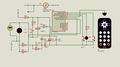
Dear Sir, I need your help again, I have the codes to control the traic to control the speed of fan using 16F676 schematic 1 working successfully and codes attached below, now I want some amendment in codes to toggle control one more triac on another port as schematic 2 attached below, Please help me /******************************************************************************** * Fan Controller * * * * This program is free software: you can redistribute it and/or modify * * it under the terms of the GNU General Public License as published by * * the Free Software Foundation, either version 3 of the License, or * * (at your option) any later version. * * * * This program is distributed in the hope that it will be useful, * * but WITHOUT ANY WARRANTY; without even the implied warranty of * * MERCHANTABILITY or FITNESS FOR A PARTICULAR PURPOSE. See the * * GNU General Public License for more details. * * * * You should have received a copy of the GNU General Public License * * along with this program. If not, see <https://www.gnu.org/licenses/>. * * * * Date : Friday, 21 January 2011 * * Author : C.V.Niras/VU3CNS * * Copyright : (C) 2010 C. V. Niras * * Email : cvniras@gmail.com * * Processor : 12F675 * * First Release : 23/01/2011 * * Ver : 0.7 * * Change History: * * Rev Date Description * * 0.5 06/03/2011 First stable release * * 0.6 08/03/2011 Bug fixed - Can't swich on by CH+, when turned * * off by set speed to 0 * * 0.7 14/06/2011 Trigger off delayed for full speed (low firing * * angle) to reach the TRIAC latch current * * * *********************************************************************************/ #include <pic.h> #include "type_def.h" #include "remote_commands.h" #if defined _12F675 __CONFIG(WDTDIS & MCLRDIS & INTIO & BORDIS & UNPROTECT & PWRTEN); #define IsIRDataBitHigh() GPIO3 == 0 // Inverted logic #define SW_UP _GPIO,0 // Up switch #define SW_DN _GPIO,2 // Down switch #define LEDOn() GPIO1 = 1 // LED #define LEDOff() GPIO1 = 0 #define TriacOn() GPIO5 = 0 // Triac #define TriacOff() GPIObits.GPIO5 = 1 #define TRIAC GPIO5 // Triac pin #endif #if defined _16F676 __CONFIG(WDTDIS & MCLRDIS & INTOSCIO & BORDIS & UNPROTECT & PWRTEN); #define GPIO PORTA #define TRISIO TRISA #define GPIF RAIF #define GPIE RAIE #define IsIRDataBitHigh() PORTAbits.RA3 == 0 // Inverted logic #define SW_UP _PORTA,0 // Up switch #define SW_DN _PORTA,2 // Down switch #define LEDOn() PORTAbits.RA1 = 1 // LED #define LEDOff() PORTAbits.RA1 = 0 #define TriacOn() PORTAbits.RA5 = 0 // Triac #define TriacOff() PORTAbits.RA5 = 1 #define TRIAC PORTAbits.RA5 // Triac pin #endif __EEPROM_DATA(5, 1, 1, 255, 255, 255, 255, 255); __IDLOC7('0','.','7','B'); #define TIMER_ENABLE // Enable timer // -- Chip Configurations -- #define _XTAL_FREQ 4000000 #define ZC_PIN_MASK 0x10 // Pin used for zero cross detection #define IR_PIN_MASK 0x08 // IR sensor output #define TIME_COUNT 6866 // Number of Timer1 overflows in an hour #define ANY_KEY Key & 0x80 #define UP_KEY Key & 0x01 #define DN_KEY Key & 0x02 // Timer 1 is the time base, 1 bit time = 8us; the NEC physical bit time is 560us = 70 Timer 1 // The following time are set with a +/- 20% tolerance #define IR_MARK_MIN_TIME 787 #define IR_SPACE_MIN_TIME 219 #define MIN_IR_BIT_TIME 56 #define MAX_IR_BIT_TIME 84 // -- End of Chip Configurations -- #define IRRx Flag.b0 // New IR bit received #define IRNewHit Flag.b1 // A new IR command received #define Error Flag.b2 // General error flag #define IRCmdRepeat Flag.b3 // A IR repeat command received #define StartFan Flag.b4 // Indicate to start the fan #define EEPromWrite Flag.b5 // Indicate to write to EEPROM #define UnknownCmd Flag.b6 // Unused IR command #define EETimeUpdate Flag1.b0 // Indicate to update time in eeprom #define IR05Seconds Flag1.b1 // A 0.5 seconds of IR inactivity, used to clear IR command repeate flag #define ClearLED Flag1.b2 // Need to turn off LED #define FanOn Status.b0 // Fan Running #define TimerRunning Status.b1 // Timer Running #define AddZeroToIRData() IRData._dword >>= 1 // Add a 0 bit to IR data #define AddOneToIRData() IRData._dword >>= 1; IRData._dword |= 0x80000000 // Add a 1 bit to IR data // NEC IR protocol states typedef enum _NEC_STATES { IR_IDLE, IR_MARK, IR_SPACE, IR_HIGH, IR_LOW, IR_REPEAT } NEC_STATES; // V A R I A B L E S //const unsigned char STable[10] = {0, 157, 165, 173, 181, 188, 195, 205, 216, 252}; // Modified to latch low power (load) fans low firing angle (on full speed) const unsigned char STable[10] = {0, 157, 165, 173, 181, 188, 195, 205, 216, 234}; near volatile BYTE Flag, Flag1, Status; near NEC_STATES IRState; unsigned char IRDataCount, PhaseAngle, Speed, Time, Count; volatile near unsigned char EECounter, Ticks, Key, KeyCount; volatile unsigned int IRTime, TimeCounter; DWORD IRData; // F U N C T I O N P R O T O T Y P E S void IRHandler(void); void NECDecoder(void); void InitIR(void); void SetSpeed(void); void OffTimer(void); void OnTimer(void); void SetTimer(void); void GetEEVariables(void); void SetEEVariables(void); void KeyDelay(void); void interrupt isr(void); void Delay2s(void); // M A I N void main(void) { #asm call 0x3ff bsf STATUS, 5 movwf OSCCAL & 0x7f bcf STATUS, 5 #endasm GPIO = 0; // Clear PORT TriacOff(); // Triac off TRISIO = ZC_PIN_MASK | IR_PIN_MASK | 0x05; // IR, Zero cross and swiches WPU = 0x05; // Weak pull up enabled for wwitches IOC = ZC_PIN_MASK | IR_PIN_MASK; // Interrupt on change is enabled for GPIO2, GPIO4 ANSEL = 0x00; // All are digital i/o CMCON = 0x07; // Comparators off INTCON = 0x68; // Enable PEIE, Timer0, Port change interrupts OPTION_REG = 0x05; // INT falling edge, Prescaler 1:64 T1CON = 0x31; // Prescaler 1:8, internal clk, TMR1ON LEDOn(); Flag._byte = 0; // Initialise flags and variables Flag1._byte = 0; InitIR(); GetEEVariables(); // Read variables eeprom IRState = IR_IDLE; // Init IR state if(FanOn) StartFan = 1; FanOn = 0; // This created a fresh start #ifdef TIMER_ENABLE if(TimerRunning) // If already started, set the time again SetTimer(); #endif GIE = 1; // Enable interrupts SetSpeed(); // Set the speed LEDOff(); // Turn off LED Count = Time << 1; // Count = Time * 2, i.e turn on/off Ticks = 0; do { NECDecoder(); // Decode NEC formatted IR data if(IRNewHit) // Is any new data? { IRNewHit = 0; // Y. Clear flag IRHandler(); // Do the command } if(IRCmdRepeat) // As long as the repeat command present { // do not turn of LED IRCmdRepeat = 0; Ticks = 0; // for the same clear Ticks } if(EEPromWrite) { EEPromWrite = 0; // Clear eeprom update flag SetEEVariables(); // Write variables if necessory } if(ClearLED) { if(Ticks & 0x20) // If remote command received, turn off LED after only { // few ms (~320ms) ClearLED = 0; LEDOff(); } } #ifdef TIMER_ENABLE else if(TimerRunning && (Ticks & 0x40)) // If timer is running and a short time expired (640ms) { // used to blink LED to show the time remaining if(Count == 0xF7) // Reload counter to show the time, after a certain time gap { Count = Time << 1; // Count = Time * 2, i.e turn on/off LEDOff(); // Ensure LED is off } if(!(--Count & 0x80)) // Blinks the LED till counter become -ve { if(Count & 0x01) { // On odd numbers in counter LED on LEDOn(); } if(!(Count & 0x01)) { // For even numbers LED off LEDOff(); } } Ticks = 0; // Reset ticks }//if(TimerRunning && (Ticks & 0x40)) #endif if(KeyCount >= 4) // Has key pressed for a short time? { if(UP_KEY) // Y. Check for Up key press { StartFan = 1; // Y. Up key pressed, inc the speed Speed++; } if(DN_KEY) // Check for a down key press { StartFan = 1; // Y. Down key pressed, decrement the speed Speed--; } if(StartFan) // If any key pressed, do the action { SetSpeed(); KeyDelay(); // Give a delay beore the next check } } }while(1); }// main // F U N C T I O N S /** The function is used to decode IR commands and make changes required */ void IRHandler(void) { if(!(IRData.byte0 ^ IRData.byte1) == 0) // Address and its compliment match { if(IRData.byte0 == 0) // Address is zero { if(!(IRData.byte2 ^ IRData.byte3) == 0) // Command and its compliment match { UnknownCmd = 0; switch(IRData.byte2) { case VOL_PLUS: StartFan = 1; Speed++; break; case VOL_MINUS: StartFan = 1; Speed--; break; case DIGIT0: Speed = 0; OffTimer(); break; case DIGIT1: StartFan = 1; Speed = 1; break; case DIGIT2: StartFan = 1; Speed = 2; break; case DIGIT3: StartFan = 1; Speed = 3; break; case DIGIT4: StartFan = 1; Speed = 4; break; case DIGIT5: StartFan = 1; Speed = 5; break; case DIGIT6: StartFan = 1; Speed = 6; break; case DIGIT7: StartFan = 1; Speed = 7; break; case DIGIT8: StartFan = 1; Speed = 8; break; case DIGIT9: StartFan = 1; Speed = 9; break; case CH_MINUS: FanOn = 0; OffTimer(); break; case CH_PLUS: if(Speed == 0) Speed++; StartFan = 1; break; case PREV: if(FanOn) Time--; SetTimer(); break; case NEXT: if(FanOn) Time++; SetTimer(); break; case EQ: OffTimer(); break; case PLAY: OnTimer(); break; default: UnknownCmd = 1; break; } if(!UnknownCmd){ LEDOn(); // A new command received ClearLED = 1; // Clear LED after a little time Ticks = 0; // Reset timer ticks SetSpeed(); } }// if((IRData.byte0 ^ IRData.byte1) == 0) }// if(IRData.byte3 == 0) }//if((IRData.byte3 ^ IRData.byte2) == 0) } /** Off the timer, without changing previous set time */ void OffTimer(void) { TimerRunning = 0; // Turn off timer Time = eeprom_read(1); // Read the eeprom, value EETimeUpdate = 1; // Update time in the eeprom EECounter = 0; // Clear the eeprom counter to update eeprom } /** On timer, start with the previous set time, if the timer is not running */ void OnTimer(void) { if(FanOn == 1) // Only start Timer when fan on { if(!TimerRunning) // Nothing to do if already started { TimerRunning = 1; // Start the timer Time = eeprom_read(1); // Get time eeprom if(Time == 0) // If zero, switch on timer with a non zero value, i.e one hour Time++; TimeCounter = TIME_COUNT; // Reload the counter EETimeUpdate = 1; // Update time in the eeprom EECounter = 0; // Clear the eeprom counter to update eeprom } } } /** Set the counters for the timer. When the counter reached zero, the fan will be turned off If the timer not running, it reload time value with the last saved value the eeprom, otherwise adjust counters as required, and clear eeprom counter to update time value in the eeprom, for the same it set a EETimeUpdate flag */ void SetTimer(void) { if(Time & 0x80) // A neg, so clear it Time = 0; if(Time > 8) Time = 8; // Max 8 hours if(FanOn == 0) // Nothing to do if fan is not running return; if(!TimerRunning && (Time != 0)) { // If decrementing, and time reached zero, on further Time = eeprom_read(1); // decrements never start the timer, only start on TimerRunning = 1; // increments, i.e when time not zero. if(Time == 0) // If zero, start with a non zero value Time++; // i.e. set to one } if(Time == 0) // Stop timer, if time is zero TimerRunning = 0; TimeCounter = TIME_COUNT; // EETimeUpdate = 1; // Update time in the eeprom EECounter = 0; // Clear the eeprom counter to update eeprom } /** Set the speed and update phase angle for a given speed. If start fan flag is set, and fan not running it starts fan will full speed for a second, then changes to ed speed. */ void SetSpeed(void) { if(Speed & 0x80) // A neg, keep it as zero Speed = 0; if(Speed >= 10) // Reach the max. Speed = 9; if(Speed == 0){ StartFan = 0; // For a zero speed, switch off FanOn = 0; } if(StartFan){ // If required, try to start the fan if(!FanOn){ // Already running? FanOn = 1; // No. Switch on fan PhaseAngle = STable[9]; // If just swiched on run it on full speed Delay2s(); // for a short time } StartFan = 0; // Clear the flag } if(FanOn == 0) OffTimer(); PhaseAngle = STable[Speed]; // Set the phase angle for the speed EECounter = 0; // Update EEPROM } /** Decode the IR data received in NEC format */ void NECDecoder(void) { static unsigned int IRBitTime, PrevIRTimer; #if 0 static unsigned char Port; if((Port ^ GPIO) & IR_PIN_MASK) // IR line changed { *((unsigned char*)&IRTime) = TMR1L; // Copy the current Timer 1 value (LSB) *((unsigned char*)&IRTime + 1) = TMR1H; // -- do -- (MSB) Port = GPIO; IRBitTime = IRTime - PrevIRTimer; PrevIRTimer = IRTime; if(IRBitTime & 0x0800) IRState = IR_IDLE; // Idle for more than 16 ms IRRx = 0; #else if(IRRx) { IRBitTime = IRTime - PrevIRTimer; PrevIRTimer = IRTime; if(IRBitTime & 0x0800) IRState = IR_IDLE; // Idle for more than 16 ms IRRx = 0; #endif Error = 0; switch(IRState) { case IR_IDLE: if(IsIRDataBitHigh()) // If it is a one, IR starting IRState++; // Now is IR_MARK IRDataCount = 0; IRData._dword = 0; break; case IR_MARK: // Now IR Mark just over if(IRBitTime < IR_MARK_MIN_TIME) { Error = 1; // Less than specified mark time } IRState++; break; case IR_SPACE: // Now IR space just over if(IRBitTime < IR_SPACE_MIN_TIME) { Error = 1; // Less than specified space time } if(IRBitTime < IR_SPACE_MIN_TIME * 2) { IRState = IR_REPEAT; // If it is less than 4.5 ms, it may be a repeat command break; } IRState++; // Space is 4.5 ms, now IR high break; case IR_HIGH: // IR high just over, check it if(((unsigned char) IRBitTime < MIN_IR_BIT_TIME) || ((unsigned char) IRBitTime > MAX_IR_BIT_TIME)) { Error = 1; // Too short or too long pulse } IRState++; break; case IR_LOW: // IR low just over, check it if(((unsigned char) IRBitTime < MIN_IR_BIT_TIME) || ((unsigned char) IRBitTime > MAX_IR_BIT_TIME * 3)) { Error = 1; // Too short or too long pulse } if((unsigned char) IRBitTime >= MIN_IR_BIT_TIME * 3) { AddOneToIRData(); // Longer low time, add a one } else { AddZeroToIRData(); // Short low time add a zero } IRDataCount++; // Increment the counter IRState--; // Now is IR High break; case IR_REPEAT: // In repeat, the 560us IR burst just over, check it now if(((unsigned char) IRBitTime < MIN_IR_BIT_TIME) || ((unsigned char) IRBitTime > MAX_IR_BIT_TIME)) { IRCmdRepeat = 0; Error = 1; } IRCmdRepeat = 1; IRState = IR_IDLE; break; }// switch(IRState) if(Error) { InitIR(); } if(IRDataCount == 32) { IRNewHit = 1; IRState = IR_IDLE; IRDataCount = 0; //IROff = 0; } IR05Seconds = 0; }// if(IRRx) } /** Initialise IR states */ void InitIR( void ) // initial IR engine { IRState = IR_IDLE; IRNewHit = 0; IRCmdRepeat = 0; IRDataCount = 0; } /** Read variables eeprom */ void GetEEVariables(void) { Speed = eeprom_read(0); Time = eeprom_read(1); Status._byte = eeprom_read(2); } /** Write to eeprom, the variables */ void SetEEVariables(void) { // Compare with the eeprom variables and update if necessory if(Speed != eeprom_read(0)) eeprom_write(0, Speed); if(EETimeUpdate) // Time may change while running, so only update { // if user make changes if(Time != eeprom_read(1)) eeprom_write(1, Time); EETimeUpdate = 0; } if(Status._byte != eeprom_read(2)) eeprom_write(2, Status._byte); } /** Create a 2 seconds delay, used to start the fan */ void Delay2s(void) { unsigned char Count; Count = 200; // Make a 200 x 10 ms delay while(--Count != 0) __delay_ms(10); } /** Delay after a key press. This function retuns after a specified time or when no key pressed down */ void KeyDelay(void) { unsigned char ms; ms = 250; // 500 ms delay do { if(!ANY_KEY) // If key released, return break; __delay_ms(2); }while(--ms != 0); } void interrupt isr(void) { static unsigned char PortStatus, PortChanges; if(GPIF) { PortChanges = PortStatus; // Copy the previous value PortStatus = GPIO; // Update PortStatus GPIF = 0; // Clear interrrupt PortChanges ^= PortStatus; // Find the differences if(PortChanges & ZC_PIN_MASK) // Zero cross { tmr0 = PhaseAngle; // Phase angle is controlled via tmr0, on interrupt it trigger if(FanOn && (PhaseAngle >= STable[9])){ // For full speed hold trigger now, and tmr0 interrupt (delayed TriacOn(); // to reach TRIAC holding current) clear the trigger } Ticks++; // Ticks @ 10 ms { #asm INCFSZ _KeyCount,W // Inc Key Count, but not beyond 255 MOVWF _KeyCount CLRW // Clear W BTFSS SW_UP // Up Key pressed? MOVLW 0x81 // Y. Load W with 0x81 BTFSS SW_DN // Down Key pressed? MOVLW 0x82 // Y. Load W with 0x82 MOVWF _Key // Save W to Key BTFSS _Key,7 // Has any key pressed? CLRF _KeyCount // N. Clear the counter #endasm } }//if(PortChanges & ZC_PIN_MASK) if(PortChanges & IR_PIN_MASK) // IR line changed { *((unsigned char*)&IRTime) = TMR1L; // Copy the current Timer 1 value (LSB) *((unsigned char*)&IRTime + 1) = TMR1H; // -- do -- (MSB) IRRx = 1; } } if(T0IF) // Interrupt depends on phase angle (tmr0 is set by phase angle) { if(FanOn){ TriacOn(); // Triac triggered } T0IF = 0; // Clear flag NOP(); NOP(); NOP(); NOP(); TriacOff(); // Triac off, beacuse already triggered }//if(T0IF) if(TMR1IF) // @ 524ms; This interrupt is not set, but polled { // with other interrupts TMR1IF = 0; #ifdef TIMER_ENABLE if(TimerRunning && (--TimeCounter == 0)) // If timer running, decrement counter { TimeCounter = TIME_COUNT; // Reload counter if(--Time == 0) // The time expired, switch off fan and counter { OffTimer(); // Switch off timer FanOn = 0; } } #endif { #asm INCFSZ _EECounter,W // Inc eeprom timer, but not beyond 255 MOVWF _EECounter #endasm } if(EECounter == 8) // After 4 seconds since clearing the counter EEPromWrite = 1; // set eeprom write flag if(IR05Seconds) // After 0.5 seconds of inactivity IRCmdRepeat = 0; // clear the repeat command IR05Seconds = 1; }//if(TMR1IF) }
what will change in codes:
Sziasztok!
Készítettem egy stoppert. Abban tudnátok segíteni, hogy az óra miért siet? 1 óra alatt 11 másodpercet siet.
Ha a PR2-t 249-ről 250-re állítom, akkor meg késik, óránként 7 másodpercet.
PIC16F628A. Belső 4 Mhz órával.
Én így állítottam be:
(Részlet a programból)
void __interrupt() megszak (void)
{
if(PIR1bits.TMR2IF)
{
if(mpcount==100){mpcount=0;mpflag = 1;} // lejárt az 1 sec
PIR1bits.TMR2IF=0;
}
}
void main (void)
{
PCONbits.OSCF=1; // a bels? oszc. 4 Mhz
OPTION_REG = 0x55; // Set tmr0 configuration and enable PORTB pullups
INTCON = 0b11000000; // ' Enable global interrupts, Disables all peripheral interrupts, disable timer0 interrupt
CMCON = 0x07 ; // analóg komparátorok kikapcsolva, RA0-1 digitális port!
PORTB = 0b00000111;
PORTA = 0;
TRISA = 0b00100000; // RA0, RA7 port bemenet, relé vagy LED
TRISB = 0b00001111; // RB2 és RB3 bemenet, a többi kimenet
// timer2 beállítása
PR2=249; //timer2 250órajel után ujrakezdi a számolást
T2CON= 0b01001101 ; //4 el?osztó modul on 10 utóosztó
PIE1bits.TMR2IE=1; // tmr2 irq enable
Köszönöm szépen!
Hajónapló kiegészítés:
Az új kontrollerekben a Timer0 modul 8 bites üzemmódban hasonlóan működik mint a Timer2, a tmr0H regiszter mint periódus regiszter funkcionál. Az ehhez kapcsolódó számítást is tudja már a program, lásd melléklet.
A frissített változatok elérhetőek itt: PICTimerCalculator - pCloud mappa.
Telepítéshez semmi extra nem kell. Törlöd a régit, az újat a helyére másolod.
Timer2 esetén van ilyen opció. Timer0 és 1 esetén nincs, marad a preload számítási táblázat.
tmr0 esetén van 8 vagy 16 bit, előosztó, utóosztó, előtöltési lehetőség. 16 bites üzemmód esetén:
16 [prescaler lehetőségek] * 16 [postscaler lehetőségek] * 65536 [preload lehetőség]. Mire ezeken végigszalad a program, lemegy a nap. Pláne azoknál, akik nem kvantumszámítógéppel bírnak, rájuk is kell gondolni. Aki tudja mire való és hogyan kell használni az előtöltést hasznos lehet így is, aki nem, annak lényegtelen a dolog.
szerk.:
A cikk, ahol bemutatom a programot, elbírálás alatt. A hozzászólás módosítva: Feb 10, 2022
De abban mégis kérném a segítségeteket, hogy miért van az, hogy a stopper szépen számol másodpercenként, akár másfél, két percig is, utána valamiért várakozik 2-3 másodpercet, majd újra szépen fut. Mi lehet ennek az oka?
#include <xc.h> #include <stdio.h> #include <string.h> #include <stdlib.h> //#define _XTAL_FREQ 4000000 ; #pragma config FOSC = INTOSCIO // Oscillator ion bits (RC oscillator) #pragma config WDTE = OFF // Watchdog Timer Enable bit (WDT disabled) #pragma config PWRTE = OFF // Power-up Timer Enable bit (PWRT disabled) #pragma config BOREN = OFF // Brown-out Reset Enable bit (BOR disabled) #pragma config CP = OFF // Flash Program Memory Code Protection bit (Code protection off) #pragma config MCLRE = ON #pragma config LVP = OFF #define bnyomogomb PORTBbits.RB2 #define jnyomogomb PORTBbits.RB1 #define oragomb PORTBbits.RB0; #define valtas PORTBbits.RB3 #define __delay_ms(x) _delay((unsigned long)((x)*(8000000/4000.0))) // set up the timing for the LCD delays #define LCD_delay 0.05 // ~5mS #define LCD_Startup 17 // ~15mS // Command set for Hitachi 44780U LCD display controller #define LCD_CLEAR 0x01 // It clears everythings #define LCD_HOME 0x02 // set the cursor to first line and first row #define LCD_CURSOR_BACK 0x10 // moves curson one position back #define LCD_CURSOR_FWD 0x14 //moves curson one position forward #define LCD_PAN_LEFT 0x18 // used to scroll text left side to scroll text #define LCD_PAN_RIGHT 0x1C // used to scroll text right side to scroll text #define LCD_CURSOR_OFF 0x0C // stops display curson on screen #define LCD_CURSOR_ON 0x0E // turns on cursor display #define LCD_CURSOR_BLINK 0x0F // curson keeps blinking #define LCD_CURSOR_LINE2 0xC0 // move curson to scond line or second row // display controller setup commands page 46 of Hitachi datasheet #define FUNCTION_SET 0x2C // 4 bit interface, 2 lines, 5x10 font #define ENTRY_MODE 0x06 // increment mode #define DISPLAY_SETUP 0x0C // display on, cursor off, blink offd #define LCDLine1() LCDPutCmd(LCD_HOME) // legacy support #define LCDLine2() LCDPutCmd(LCD_CURSOR_LINE2) // legacy support #define shift_cursor() LCDPutCmd(LCD_CURSOR_FWD) // legacy support #define cursor_on() LCDPutCmd(LCD_CURSOR_ON) // legacy support #define DisplayClr() LCDPutCmd(LCD_CLEAR) // Legacy support //---------------------------------------------------------------------- // Definitions specific to the PICDEM 2 Plus // These apply to the Black (2011) version. //---------------------------------------------------------------------- // single bit for ing command register or data register #define instr 0 #define data 1 // These #defines create the pin connections to the LCD in case they are changed on a future demo board #define LCD_PORT PORTA #define LCD_PWR 1 // LCD power pin #define LCD_EN PORTAbits.RA6 // LCD enable #define LCD_RW 0 // LCD read/write line #define LCD_RS PORTAbits.RA7 // LCD register line #define led PORTBbits.RB5 #define ledgomb PORTBbits.RB7 #define NB_LINES 2 // Number of display lines #define NB_COL 16 // Number of characters per line void LCD_Initialize(void); void LCDPutChar(char ch); void LCDPutCmd(char ch); void LCDPutStr(const char *); void LCDWriteNibble(char ch, char rs); void LCDGoto(char pos, char ln); void UpdateTimer (void) ; //unsigned int k=0; /**/ unsigned char t2cnt,mpflag,mpcount,villog, bgomb, bgombold, jgomb, jgombold, flag,bkeycnt=0, jkeycnt=0, r1cnt,r2cnt,time1=60, time2=30, s,ki, bk=0, jk=0, bv=51, jv=51, ogomb, ora, min, sec=0, l, tsec; void __interrupt() megszak (void) { if(PIR1bits.TMR2IF) { t2cnt++; if(t2cnt==10){t2cnt=0;flag |=1;}// lejárt 0,1 sec frissülhet a f?progi mpcount++ ; if(mpcount==100){mpcount=0;mpflag = 1;} // lejárt az 1 sec PIR1bits.TMR2IF=0; } } void main (void) { PCONbits.OSCF=1; // a bels? oszc. 4 Mhz OPTION_REG = 0x55; // Set tmr0 configuration and enable PORTB pullups INTCON = 0b11000000; // ' Enable global interrupts, Disables all peripheral interrupts, disable timer0 interrupt CMCON = 0x07 ; // analóg komparátorok kikapcsolva, RA0-1 digitális port! PORTB = 0b00000111; PORTA = 0; TRISA = 0b00100000; // RA0, RA7 port bemenet, relé vagy LED TRISB = 0b00001111; // RB2 és RB3 bemenet, a többi kimenet // timer2 beállítása PR2=249; //timer2 250órajel után ujrakezdi a számolást T2CON= 0b01001101 ; //4 el?osztó modul on 10 utóosztó PIE1bits.TMR2IE=1; // tmr2 irq enable LCD_Initialize(); while(1) { if(mpflag) { villog = ~villog ; //LED villogtató led = villog ; mpflag = 0 ; } if(flag) // 0.1 sec lejárt f?program frissítése { flag=0; bgombold = bgomb ; bgomb = bnyomogomb ; jgombold = jgomb ; jgomb = jnyomogomb ; ogomb =oragomb; if(bgomb == 0 & ogomb ==0) l=1; if (l==1) { UpdateTimer (); LCDGoto(4,1); LCDPutChar((ora/10)+0x30); LCDPutChar((ora%10)+0x30); LCDPutChar(0x3A); LCDPutChar((min/10)+0x30); LCDPutChar((min%10)+0x30); LCDPutChar(0x3A); LCDPutChar((sec/10)+0x30); LCDPutChar((sec%10)+0x30); } if (bgomb == 0 & bgombold == 1 /*& bv>50 */) //lenyomtuk a gombot, magasból alacsony szintre vált a bemenet { bv=0; if (valtas) bk--; else bk++; bkeycnt=0; } bv++; if(bgomb == 0) //ha még mindig nyomva { bkeycnt++; } if (bgomb == 1 & bgombold == 0) //elengedtük a gombot, alacsonyból magas szintre vált a bemenet { if(bkeycnt>50) //sokáig nyomva volt { ledgomb=1; bk=0; LCDGoto(0,0); LCDPutChar(0x30); LCDPutStr (" "); } else { LCDGoto(0,0); if(bk<10) LCDPutChar(bk+0x30); else {LCDPutChar((bk/10)+0x30); LCDPutChar((bk%10)+0x30); } } } if (jgomb == 0 & jgombold == 1 /*& jv>50 */) //lenyomtuk a gombot, magasból alacsony szintre vált a bemenet { jv=0; if (valtas) jk--; else jk++; jkeycnt=0; } jv++; if(jgomb == 0) //ha még mindig nyomva { jkeycnt++; } if (jgomb == 1 & jgombold == 0) //elengedtük a gombot, alacsonyból magas szintre vált a bemenet { if(jkeycnt>50) //sokáig nyomva volt { ledgomb=1; jk=0; LCDGoto(14,0); LCDPutChar(0x30); LCDPutStr (" "); } else { LCDGoto(14,0); if(jk<10) LCDPutChar(jk+0x30); else {LCDPutChar((jk/10)+0x30); LCDPutChar((jk%10)+0x30); } } } if (jk==bk & bk>0) { LCDGoto(5,0); LCDPutStr ("EGYENLo"); } if (abs(jk-bk)>=10) {LCDGoto(5,0); LCDPutStr ("MOCSING"); } if (jk!=bk & abs(jk-bk)<10) {LCDGoto(5,0); LCDPutStr (" ");} } } } void LCD_Initialize() { // clear latches before enabling TRIS bits //LCD_PORT = 0; PORTAbits.RA0=0; PORTAbits.RA1=0; PORTAbits.RA2=0; PORTAbits.RA3=0; PORTAbits.RA6=0; PORTAbits.RA7=0; TRISA = 0b00100000; // power up the LCD //LCD_PWR = 1; // required by display controller to allow power to stabilize __delay_ms(LCD_Startup); // required by display initialization LCDPutCmd(0x32); // set interface size, # of lines and font LCDPutCmd(FUNCTION_SET); // turn on display and sets up cursor LCDPutCmd(DISPLAY_SETUP); DisplayClr(); // set cursor movement direction LCDPutCmd(ENTRY_MODE); } void LCDWriteNibble(char ch, char rs) { // always send the upper nibble ch = (ch >> 4); // mask off the nibble to be transmitted ch = (ch & 0x0F); // clear the lower half of LCD_PORT LCD_PORT = (LCD_PORT & 0xF0); // move the nibble onto LCD_PORT LCD_PORT = (LCD_PORT | ch); // set data/instr bit to 0 = insructions; 1 = data LCD_RS = rs; // RW - set write mode //LCD_RW = 0; // set up enable before writing nibble LCD_EN = 1; // turn off enable after write of nibble LCD_EN = 0; } void LCDPutChar(char ch) { __delay_ms(LCD_delay); //Send higher nibble first LCDWriteNibble(ch,data); //get the lower nibble ch = (ch << 4); // Now send the low nibble LCDWriteNibble(ch,data); } void LCDPutCmd(char ch) { __delay_ms(LCD_delay); //Send the higher nibble LCDWriteNibble(ch,instr); //get the lower nibble ch = (ch << 4); __delay_ms(1); //Now send the lower nibble LCDWriteNibble(ch,instr); } void LCDPutStr(const char *str) { char i=0; // While string has not been fully traveresed while (str[i]) { // Go display current char LCDPutChar(str[i++]); } } void LCDGoto(char pos,char ln) { // if incorrect line or column if ((ln > (NB_LINES-1)) || (pos > (NB_COL-1))) { // Just do nothing return; } // LCD_Goto command LCDPutCmd((ln == 1) ? (0xC0 | pos) : (0x80 | pos)); // Wait for the LCD to finish __delay_ms(LCD_delay); } void UpdateTimer (void) { if(mpflag) { sec++; mpflag = 0 ; } if (sec==60) {sec=0; min++;} if (min==60) {min=0; ora++;} if (ora==24) ora= 0; }
PIC16F877A-an fut ez a megoldás. Én csak a PORT-okat írtam át.
Most csináltam egy olyat, hogy a PORTA-n van az LCD, a gombok a PORTB-n. Mindent lecsupaszítottam, csak a Hello World-t kellene kiírnia, de már ezt se tudja. Nem tudom, mi lehet a baja. 
#include <xc.h> #include <stdio.h> #include <string.h> #include <stdlib.h> #pragma config FOSC = INTOSCIO // Oscillator ion bits (RC oscillator) #pragma config WDTE = OFF // Watchdog Timer Enable bit (WDT disabled) #pragma config PWRTE = OFF // Power-up Timer Enable bit (PWRT disabled) #pragma config BOREN = OFF // Brown-out Reset Enable bit (BOR disabled) #pragma config CP = OFF // Flash Program Memory Code Protection bit (Code protection off) #pragma config MCLRE = ON #pragma config LVP = OFF #define bgomb PORTBbits.RB2 #define jobbgomb PORTBbits.RB1 #define oragomb PORTAbits.RB0 #define valtas PORTAbits.RA7 #define __delay_ms(x) _delay((unsigned long)((x)*(8000000/4000.0))) // set up the timing for the LCD delays #define LCD_delay 5 // ~5mS #define LCD_Startup 15 // ~15mS // Command set for Hitachi 44780U LCD display controller #define LCD_CLEAR 0x01 // It clears everythings #define LCD_HOME 0x02 // set the cursor to first line and first row #define LCD_CURSOR_BACK 0x10 // moves curson one position back #define LCD_CURSOR_FWD 0x14 //moves curson one position forward #define LCD_PAN_LEFT 0x18 // used to scroll text left side to scroll text #define LCD_PAN_RIGHT 0x1C // used to scroll text right side to scroll text #define LCD_CURSOR_OFF 0x0C // stops display curson on screen #define LCD_CURSOR_ON 0x0E // turns on cursor display #define LCD_CURSOR_BLINK 0x0F // curson keeps blinking #define LCD_CURSOR_LINE2 0xC0 // move curson to scond line or second row // display controller setup commands page 46 of Hitachi datasheet #define FUNCTION_SET 0x2C // 4 bit interface, 2 lines, 5x10 font #define ENTRY_MODE 0x06 // increment mode #define DISPLAY_SETUP 0x0C // display on, cursor off, blink offd #define LCDLine1() LCDPutCmd(LCD_HOME) // legacy support #define LCDLine2() LCDPutCmd(LCD_CURSOR_LINE2) // legacy support #define shift_cursor() LCDPutCmd(LCD_CURSOR_FWD) // legacy support #define cursor_on() LCDPutCmd(LCD_CURSOR_ON) // legacy support #define DisplayClr() LCDPutCmd(LCD_CLEAR) // Legacy support // single bit for ing command register or data register #define instr 0 #define data 1 // These #defines create the pin connections to the LCD in case they are changed on a future demo board #define LCD_PORT PORTA #define LCD_PWR 1 // LCD power pin #define LCD_EN PORTAbits.RA6 // LCD enable #define LCD_RW 0 // LCD read/write line #define LCD_RS PORTAbits.RA4 // LCD register line #define led PORTAbits.RA7 #define NB_LINES 2 // Number of display lines #define NB_COL 16 // Number of characters per line void LCD_Initialize(void); void LCDPutChar(char ch); void LCDPutCmd(char ch); void LCDPutStr(const char *); void LCDWriteNibble(char ch, char rs); void LCDGoto(char pos, char ln); unsigned int k=0; /**/ unsigned char t2cnt,mpflag,mpcount,villog, bnyomogomb, bgombold,flag,keycnt,r1cnt,r2cnt,time1=60, time2=30, s,ki, max; void main (void) { PCONbits.OSCF=1; // a bels? oszc. 4 Mhz OPTION_REG = 0x55; // Set tmr0 configuration and enable PORTB pullups CMCON = 0x07 ; // analóg komparátorok kikapcsolva, RA0-1 digitális port! PORTB = 0b00000111; PORTA = 0; TRISA = 0b00000000; // RA0, RA7 port bemenet, relé vagy LED TRISB = 0b00001111; // RB2 és RB3 bemenet, a többi kimenet LCD_Initialize(); while(1) { LCDPutStr(" Hello World!"); __delay_ms(3000); } } void LCD_Initialize() { // clear latches before enabling TRIS bits LCD_PORT = 0; TRISA = 0b00000000; // power up the LCD //LCD_PWR = 1; // required by display controller to allow power to stabilize __delay_ms(LCD_Startup); // required by display initialization LCDPutCmd(0x32); // set interface size, # of lines and font LCDPutCmd(FUNCTION_SET); // turn on display and sets up cursor LCDPutCmd(DISPLAY_SETUP); DisplayClr(); // set cursor movement direction LCDPutCmd(ENTRY_MODE); } void LCDWriteNibble(char ch, char rs) { // always send the upper nibble ch = (ch >> 4); // mask off the nibble to be transmitted ch = (ch & 0x0F); // clear the lower half of LCD_PORT LCD_PORT = (LCD_PORT & 0xF0); // move the nibble onto LCD_PORT LCD_PORT = (LCD_PORT | ch); // set data/instr bit to 0 = insructions; 1 = data LCD_RS = rs; // RW - set write mode //LCD_RW = 0; // set up enable before writing nibble LCD_EN = 1; // turn off enable after write of nibble LCD_EN = 0; } void LCDPutChar(char ch) { __delay_ms(LCD_delay); //Send higher nibble first LCDWriteNibble(ch,data); //get the lower nibble ch = (ch << 4); // Now send the low nibble LCDWriteNibble(ch,data); } void LCDPutCmd(char ch) { __delay_ms(LCD_delay); //Send the higher nibble LCDWriteNibble(ch,instr); //get the lower nibble ch = (ch << 4); __delay_ms(1); //Now send the lower nibble LCDWriteNibble(ch,instr); } void LCDPutStr(const char *str) { char i=0; // While string has not been fully traveresed while (str[i]) { // Go display current char LCDPutChar(str[i++]); } } void LCDGoto(char pos,char ln) { // if incorrect line or column if ((ln > (NB_LINES-1)) || (pos > (NB_COL-1))) { // Just do nothing return; } // LCD_Goto command LCDPutCmd((ln == 1) ? (0xC0 | pos) : (0x80 | pos)); // Wait for the LCD to finish __delay_ms(LCD_delay); }
Sziasztok!
Tudnátok segíteni, hogy az LCD-re miért nem írja ki a "k" értékét? Szerintem az LCD iniciálásánál lehet a probléma az LCD_PORT-nál. Nem igazán értem, hogy ott mit kellene megadni.
Köszönöm!
#include <xc.h> //#include <stdio.h> //#include <string.h> //#include <stdlib.h> //#define _XTAL_FREQ 4000000 ; #pragma config FOSC = INTOSCIO // Oscillator ion bits (RC oscillator) #pragma config WDTE = OFF // Watchdog Timer Enable bit (WDT disabled) #pragma config PWRTE = OFF // Power-up Timer Enable bit (PWRT disabled) #pragma config BOREN = OFF // Brown-out Reset Enable bit (BOR disabled) #pragma config CP = OFF // Flash Program Memory Code Protection bit (Code protection off) #pragma config MCLRE = ON #pragma config LVP = OFF #define bgomb PORTBbits.RB2 #define jobbgomb PORTBbits.RB1 #define oragomb PORTAbits.RB0 #define valtas PORTAbits.RA7 #define __delay_ms(x) _delay((unsigned long)((x)*(4000000/4000.0))) // set up the timing for the LCD delays #define LCD_delay 5 // ~5mS #define LCD_Startup 15 // ~15mS // Command set for Hitachi 44780U LCD display controller #define LCD_CLEAR 0x01 // It clears everythings #define LCD_HOME 0x02 // set the cursor to first line and first row #define LCD_CURSOR_BACK 0x10 // moves curson one position back #define LCD_CURSOR_FWD 0x14 //moves curson one position forward #define LCD_PAN_LEFT 0x18 // used to scroll text left side to scroll text #define LCD_PAN_RIGHT 0x1C // used to scroll text right side to scroll text #define LCD_CURSOR_OFF 0x0C // stops display curson on screen #define LCD_CURSOR_ON 0x0E // turns on cursor display #define LCD_CURSOR_BLINK 0x0F // curson keeps blinking #define LCD_CURSOR_LINE2 0xC0 // move curson to scond line or second row // display controller setup commands page 46 of Hitachi datasheet #define FUNCTION_SET 0x2C // 4 bit interface, 2 lines, 5x10 font #define ENTRY_MODE 0x06 // increment mode #define DISPLAY_SETUP 0x0C // display on, cursor off, blink offd #define LCDLine1() LCDPutCmd(LCD_HOME) // legacy support #define LCDLine2() LCDPutCmd(LCD_CURSOR_LINE2) // legacy support #define shift_cursor() LCDPutCmd(LCD_CURSOR_FWD) // legacy support #define cursor_on() LCDPutCmd(LCD_CURSOR_ON) // legacy support #define DisplayClr() LCDPutCmd(LCD_CLEAR) // Legacy support //---------------------------------------------------------------------- // Definitions specific to the PICDEM 2 Plus // These apply to the Black (2011) version. //---------------------------------------------------------------------- // single bit for ing command register or data register #define instr 0 #define data 1 // These #defines create the pin connections to the LCD in case they are changed on a future demo board #define LCD_PORT PORTBbits.RB4, PORTBbits.RB5,PORTBbits.RB6,PORTBbits.RB7 #define LCD_PWR 1 // LCD power pin #define LCD_EN PORTBbits.RB3 // LCD enable #define LCD_RW 0 // LCD read/write line #define LCD_RS PORTAbits.RA0 // LCD register line #define NB_LINES 2 // Number of display lines #define NB_COL 16 // Number of characters per line void LCD_Initialize(void); void LCDPutChar(char ch); void LCDPutCmd(char ch); void LCDPutStr(const char *); void LCDWriteNibble(char ch, char rs); void LCDGoto(char pos, char ln); unsigned int k=0; void LCD_Initialize() { // clear latches before enabling TRIS bits LCD_PORT = 0; TRISB = 0b00000111; // power up the LCD //LCD_PWR = 1; // required by display controller to allow power to stabilize __delay_ms(LCD_Startup); // required by display initialization LCDPutCmd(0x32); // set interface size, # of lines and font LCDPutCmd(FUNCTION_SET); // turn on display and sets up cursor LCDPutCmd(DISPLAY_SETUP); DisplayClr(); // set cursor movement direction LCDPutCmd(ENTRY_MODE); } void LCDWriteNibble(char ch, char rs) { // always send the upper nibble ch = (ch >> 4); // mask off the nibble to be transmitted ch = (ch & 0x0F); // clear the lower half of LCD_PORT LCD_PORT = (LCD_PORT & 0xF0); // move the nibble onto LCD_PORT LCD_PORT = (LCD_PORT | ch); // set data/instr bit to 0 = insructions; 1 = data LCD_RS = rs; // RW - set write mode //LCD_RW = 0; // set up enable before writing nibble LCD_EN = 1; // turn off enable after write of nibble LCD_EN = 0; } void LCDPutChar(char ch) { __delay_ms(LCD_delay); //Send higher nibble first LCDWriteNibble(ch,data); //get the lower nibble ch = (ch << 4); // Now send the low nibble LCDWriteNibble(ch,data); } void LCDPutCmd(char ch) { __delay_ms(LCD_delay); //Send the higher nibble LCDWriteNibble(ch,instr); //get the lower nibble ch = (ch << 4); __delay_ms(1); //Now send the lower nibble LCDWriteNibble(ch,instr); } void LCDPutStr(const char *str) { char i=0; // While string has not been fully traveresed while (str[i]) { // Go display current char LCDPutChar(str[i++]); } } void LCDGoto(char pos,char ln) { // if incorrect line or column if ((ln > (NB_LINES-1)) || (pos > (NB_COL-1))) { // Just do nothing return; } // LCD_Goto command LCDPutCmd((ln == 1) ? (0xC0 | pos) : (0x80 | pos)); // Wait for the LCD to finish __delay_ms(LCD_delay); } /**/ unsigned char t2cnt,mpflag,mpcount,villog, bnyomogomb, bgombold,flag,keycnt,r1cnt,r2cnt,time1=60, time2=30, s,ki, led, max; void __interrupt() megszak (void) { if(PIR1bits.TMR2IF) { t2cnt++; if(t2cnt==10){t2cnt=0;flag |=1;}// lejárt 0,1 sec frissülhet a f?progi mpcount++ ; if(mpcount==100){mpcount=0;mpflag = 1;} // lejárt az 1 sec PIR1bits.TMR2IF=0; } } void main (void) { PCONbits.OSCF=1; // a bels? oszc. 4 Mhz OPTION_REG = 0x55; // Set tmr0 configuration and enable PORTB pullups INTCON = 0b11000000; // ' Enable global interrupts, Disables all peripheral interrupts, disable timer0 interrupt CMCON = 0x07 ; // analóg komparátorok kikapcsolva, RA0-1 digitális port! PORTB = 0b00000111; TRISA = 0b10000000; // RA0, RA7 port bemenet, relé vagy LED TRISB = 0b00000111; // RB2 és RB3 bemenet, a többi kimenet // timer2 beállítása PR2=249; //timer2 250órajel után ujrakezdi a számolást T2CON= 0b01001101 ; //4 el?osztó modul on 10 utóosztó PIE1bits.TMR2IE=1; // tmr2 irq enable LCD_Initialize(); while(1) { if(mpflag) { villog = ~villog ; //LED villogtató mpflag = 0 ; } if(flag) // 0.1 sec lejárt f?program frissítése { flag=0; bgombold = bgomb ; bgomb = bnyomogomb ; if (bgomb == 0 & bgombold == 1) //lenyomtuk a gombot, magasból alacsony szintre vált a bemenet { LCDGoto(3,1); LCDPutStr(" SLTisztaterter"); } if(bgomb == 0) //ha még mindig nyomva { keycnt++; if(keycnt>5){led=1; // rele2=1; r1cnt++ ; r2cnt++;} //0.5 secnél led on késleltetés frissítés felfüggesztve if (keycnt > max) //100x0.1 mp, azaz 10 mp az alap id?, ha ezt túllépjük, akkor növeljük a bekapcsolási id?t {keycnt = max; led=0; } } if (bgomb == 1 & bgombold == 0) //elengedtük a gombot, alacsonyból magas szintre vált a bemenet { if(keycnt>5) //sokáig nyomva volt { k==0; } k++; LCDGoto(3,1); LCDPutStr(" SL Tisztaterte"); if(k<10) LCDPutChar(k+0x30); else {LCDPutChar((k/10)+0x30); LCDPutChar((k%10)+0x30); } } } } }
Melyik az a program ami nem úgy néz ki ? A villogó tmr0 nevű lcd példa csak segéd változót használ a kijelző "mozgatásához" a megszakítás még csak makróhívást sem tartalmaz , most tegyél fel olyan példát ami szerintünk jó. A hozzászólás módosítva: Dec 25, 2020
Idézet:
„Azt írod, nem megszakításból csinálod a multiplexelést,” Ezt hol írtam ?
Mi az ami zavaros ? Azt írtam hogy a multiplex a tmr0 ból segédváltozóval van vezérelve , az "óra" meg a tmr2 ből ... Egyébként meg az a lényeg hogy a kérdező megkapta a választ a többivel meg nem törődünk ... A hozzászólás módosítva: Dec 25, 2020
Láttad a fájlt amit feltettem ? Ahhoz írd hozzá a tmr0-t( tuti nem fog ugatni a fordító) Egy szóval nem mondtam hogy a megszakításban akarom kezelni az LCD-t Sőt a multiplex vezérléseim is csak az időzítést (léptetést) kapják a megszakításból teljesen külön makróban dolgoznak ! A villogtatásról volt szó ráadásul segédváltozóval . A hozzászólás módosítva: Dec 25, 2020
Mondjuk ez nekünk természetes hogy segédváltozóval villogtatjuk (ott van az x változó én tmr0 ból csinálnám) és ha szükség van rendes megszakításra azt a tmr2 ből intézném . De mivel "csak" menü lesz ezért elég ha időzítést használ . A hozzászólás módosítva: Dec 25, 2020
Hali!
Úgy látom a legtöbb kérdésre már választ kaptál.
Ennél a PIC-nél a Timer0 16bit-es módjánál a tmr0H egy átmeneti puffer, a tmr0L olvasásakor kerül bele az aktuális érték (azt hiszem debug-kor nem is látod számlálni a tmr0H-t), illetve a tmr0L beírásakor kerül át a valódi regiszterbe a tmr0H-ból. Így biztosítják a pontos érték kiolvasását/beírását.
Ez a puffer a timerhez tartozik, nem foglal több memóriát. Lásd adatlap.
Nekem van olyan programom, ahol fix 20ms a ciklusidő. Ezt egy timer hozza létre megszakítással. Minden művelet ebben a 20ms-ben történik (kicsit PLC szerűen), nem tudom mennyi idő alatt, sosem mértem meg. Itt semmit nem adok át a fő programnak. A fő program csak az őrkutya buksiját simogatja állandóan.
Megszakításban a hosszú időzítéseket kell kerülni, mert akkor a fő programodat úgy fogod látni, mintha akadna/lefagyna.
E sorhoz több utasítás is fordul. Menteni kell a W és a STATUS regiszterek értékét. Minimálisan 3 utasítás kell hozzá, de a fordító beállításai több munkát is adhatnak.
A bit vizsgálata valóban 1 utasítás, de a feltétel nem teljesülésekor ugrani kell, így 2 utasításnyi időt kell számolni.
Tudni kellene a fhasznált kontroller típusát. PIC18 esetén 1, PIC12- PIC16 esetén 2 utasítás.
2 utasítás.
Minimum 1 utasítás, de függ attól, hogy hova foglaltuk a változót - bankváltás.
Minimum 1 utasítás, de függ attól, hogy hova foglaltuk a változót - bankváltás.
A visszatéréskor a mentett értékeket vissza kell állítani a STAUS és a W regiszterekbe, ill. amit még előírt a fordító. Minimum 4 utasítás és még egy a retfie.
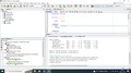
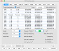
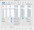
Az MpLab -ban van lehetőség programrészletek futási idejét "megmérni". Ki kell választani a Simulator -t nyomkövetőnek, újra kell fordítania kódot. A rutin elejére kell állítani a programszámlálót. Be kell állítani az órajel frekvenciáját és el kell helyezni egy töréspontot a rutin végére. A Stopwatch ablakot megnyitva láthatjuk a végrehajtott utasítások számát és idejét is. A hozzászólás módosítva: Dec 17, 2020
Még valamit nem értek, Bocsi 
Idézlek:
Idézet:
„A tmr0H-t előbb kell beírni, mert az pufferelt és a tmr0L beírásakor az is átmásolódik a Timer-be.”
A tmr0H: tmr0L az maga a számláló ha jól tudom (16biten). Hogy kell értelmezni ezt a puffer dolgot?
Gondolom az egy átmeneti tároló egy foglalt memóriaterület, de akkor nem mindegy a sorrend? Úgyis csak akkor záródik le az áttöltés ha minden bit a helyére került.
|
|